
Designed for 110kV, 66kV, 35kV and below substations, this panel integrates differential, non‑electrical, and backup protection with advanced measurement, control, and communication functions, making it the ideal choice for large‑capacity main transformers.
The Main Transformer Protection and Control Panel is designed for automation systems of substations and distribution stations with voltage levels of 110kV, 66kV, 35kV and below. It integrates communication, protection, measurement, and control functions, making it an ideal choice for large-capacity main transformers. The panel provides differential protection, non‑electrical quantity protection, backup protection for the main transformer, measuring and control functions, and communication capabilities. Three communication modes are supported: RS485, Ethernet, and fiber optic communication. Real‑time communication with the upper‑level master station enables comprehensive automation of the substation/distribution station.
Main Transformer Differential Protection Device
Provides transformer differential instantaneous overcurrent protection and percentage differential protection. The main protection coverage is internal transformer faults.
Main Transformer High‑Voltage Side Backup Protection Device
Protects the high‑voltage side bushings and external areas of the transformer. In case of a fault, it trips the high‑voltage side circuit breaker. Common protection functions include three‑stage overcurrent protection, zero‑sequence current protection, overvoltage protection, undervoltage protection, etc.
Main Transformer Low‑Voltage Side Backup Protection Device
Protects the low‑voltage side bushings and external areas of the transformer. In case of a fault, it trips the high‑voltage side circuit breaker. Common protection functions include three‑stage overcurrent protection, zero‑sequence current protection, overvoltage protection, undervoltage protection, etc.
Main Transformer Non‑Electrical Quantity Protection Device
Main functions include light gas protection, heavy gas protection, high temperature protection, overtemperature protection, pressure relief protection, etc.
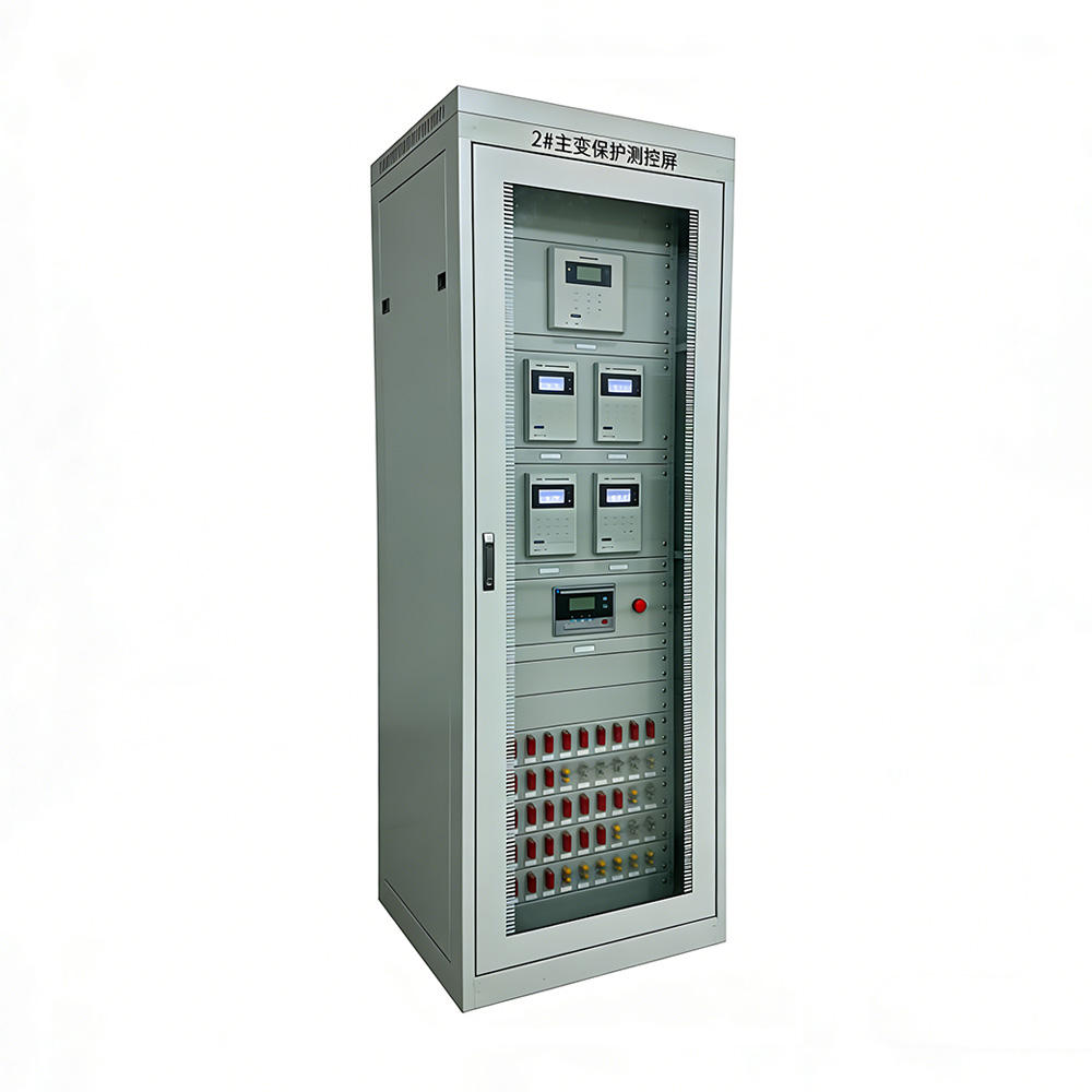
Compact and Scalable Cabinet Design
The cabinet measures 2260mm (or 2360mm) × 800mm × 600mm. Each panel can accommodate up to three layers of devices, with three devices per layer. All protection, control and automation devices are physically and spatially distributed to the primary equipment bay level of the substation. Each device operates as an independent system with its own power supply, CPU, and independent operating circuit, completing protection, measurement and control for its corresponding bay. The devices are completely independent in both hardware and software, without relying on the communication network.
High‑Performance CPU
The CPU adopts an internationally advanced DSP chip. Measures such as isolation, hardware/software filtering, watchdog circuits, anti‑interference coding, intelligent diagnostics, various interlocking/unlocking control circuits, and an anti‑vibration, anti‑interference mechanical design have been implemented to improve device reliability.
Flexible Communication System
Each device can connect directly to a computer via fieldbus for communication, or communicate with a communication manager. All collected information is uploaded to the microcomputer monitoring system through the communication manager; meanwhile, the communication manager sends received commands to the corresponding devices. The control equipment layer takes the primary equipment inside the station as the measurement and control object, analyzing the station’s requirements for information acquisition, processing and control in an object‑oriented manner. Microprocessor‑based protection and control devices are distributed as compact, highly reliable units. The devices are relatively independent and can communicate with the substation layer equipment, realizing comprehensive substation automation.
Chinese Character Display
A large‑screen LCD directly displays electrical quantities such as current, voltage, power, etc. All information about protection operations is shown on the screen, with the operation time and magnitude recorded.
Clear Indication
Seven indicator LEDs show the working status of the protection device, the status of monitoring elements, and the trip/close status of the circuit breaker.
Easy Operation
Protection enabling/disabling, setting value adjustments, data query, input detection, output testing, etc., can all be performed directly on the front panel, greatly improving operational convenience.
Strong Confidentiality & Security
Operations involving data changes (protection enabling/disabling, setting adjustments, output testing) require a password, significantly enhancing operational security.
Secure Setting Management
All protection settings are adjusted directly through the operation menu. Setting adjustments via the computer or monitoring microcomputer also require an operation password and proper authority, ensuring the security of the setting values.
Controlled Output Operation
According to the relay circuits shown in the drawings, all relay outputs can be operated directly from the front panel, but each requires its corresponding password.
Comprehensive Data Display
The measured current, bus voltage, and derived values such as line voltage, active power, reactive power, power factor, frequency, and other electrical quantities are all centrally shown on the LCD.
High‑Performance Sampling
The protection circuit and measurement circuit have independent sampling channels, ensuring both measurement accuracy and the anti‑saturation performance of the protection.
Independent Outputs
All output relays use separate channels, facilitating protection enabling/disabling. Remote close/open, protection close, protection trip, alarm, pre‑alarm and other special signal outputs are all independent.
Open Software Architecture
Via the software‑editable menu, users can query various electrical quantities collected by the protection device, check load operation status, and configure some parameters.
Event Recording
Records at least 60 recent events. Any change of major components is recorded with power‑off retention. The information can be queried in the event log.
Self‑Protection
Each circuit breaker corresponds to an independent operating circuit, allowing direct operation in an emergency. The device also provides protection for the breaker trip/close coil, preventing coil burnout due to mechanical failure.
High Immunity
The device chassis is sealed with double‑layer internal shielding, reducing electromagnetic interference.
Vibration Resistance
All boards are tightly connected via hard plug‑in connections and secured with fixing screws, preventing loosening or detachment during long‑distance transportation.
Strong Substitution Capability
With powerful functions including “four‑remote” (remote measurement, remote signalling, remote control, remote adjustment), the device can fully replace conventional relay protection. The digital input greatly reduces maintenance workload.
Flexible Design
Depending on site conditions, the panel can be designed as a centralised cabinet or distributed installation on switchgear. Reliable operation is ensured by a comprehensive self‑check system, with hardware checking down to the relay trip output, using reliable components.
Cabinet dimensions: 2260×800×600mm (or 2360×800×600mm)
Number of device layers: 3 (max. 3 devices per layer)
Differential protection device: 1 unit
High‑voltage side backup protection device: 1 unit
Low‑voltage side backup protection device: 1 unit
Non‑electrical quantity protection device: 1 unit
Communication management unit: 1 unit (optional)
Redundant power supply: 2 units (DC 110/220V or AC 220V)
Terminal blocks, wiring accessories, and cabinet lighting
