
The LCU Panel is a compact, intelligent local control unit designed for hydropower plants and pumping stations. It performs real-time data acquisition (analog, digital, temperature, and power quantities), equipment monitoring, sequence control (start/stop/emergency shutdown), and communication with upper-level SCADA systems.
Built with PLC, touch screen, surge protection, and redundant self-diagnostics, the panel ensures safe, reliable, and automated operation of generator and pump units – both locally and remotely.
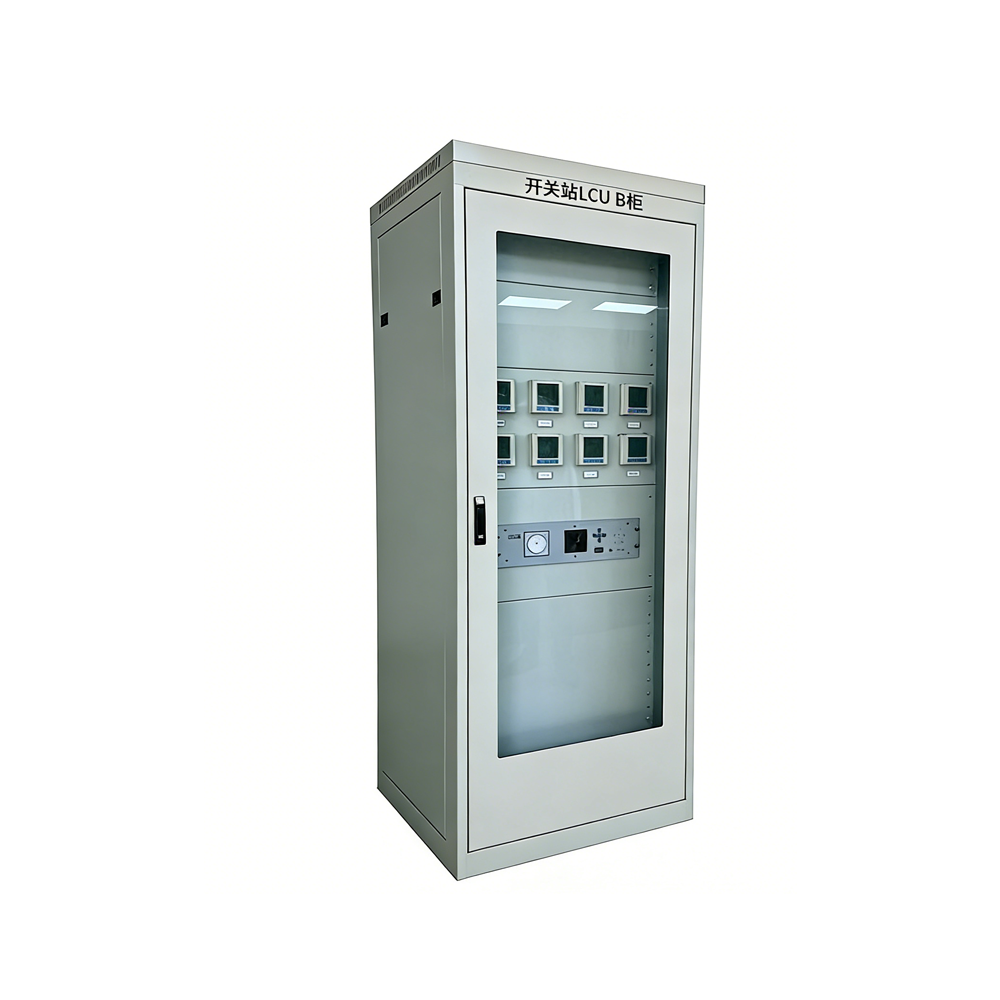
The LCU Panel is a core component of automation systems in pumping stations and hydropower plants. It integrates digital input/output modules, analog input modules, Ethernet modules, a LCD touch screen, comprehensive power acquisition meters, power transducers, intermediate relays and bases, power switches, buttons and indicators, manual/auto selector switches, operation switches, communication surge protectors, power surge protectors, cabinet body and accessories.
It provides comprehensive functions including data acquisition and processing for main and auxiliary equipment of generator units and pump sets, safe operation monitoring, control and regulation, auxiliary equipment control, data communication, and self-diagnostics. The LCU Panel is an indispensable part of modern hydropower and pumping station automation.
| Function Category | Description |
|---|---|
| Data Acquisition & Processing | Real-time acquisition, processing, and storage of operation status, parameters, and measured values of main/auxiliary equipment. Data includes analog, digital, temperature, and electric energy quantities. |
| – Analog Inputs | Electrical analog (via AC sampling: current, voltage, power, frequency, etc.) and non-electrical analog (4–20mA with WS series isolators). Processing includes loop break detection, digital filtering, error compensation, validity check, scaling, gradient calculation, limit checking and alarm. |
| – Digital Inputs | Includes SOE (Sequence of Events) and normal digital inputs. Processing: opto-isolation, hardware/software filtering, time stamping, validity check. SOE inputs are scanned at millisecond resolution. |
| – Derived Values | Logic and arithmetic results from acquired data (e.g., unit state, bus state, breaker operation count). |
| Control & Regulation | Local monitoring and control; remote control from master station; unit start/stop sequence control; ability to interrupt sequence and directly stop; emergency and accident shutdown control. |
| Control Safety | Interlock checking before execution; automatic disable of control functions upon module fault; return-check mechanism for command validation. |
| Safe Operation Monitoring | Status monitoring, event alarm & SOE, limit/gradient check and alarm, trend display, automatic audible alarm on system fault. |
| Self-Diagnostics | Online/offline hardware & software diagnostics down to board level; fault alarm, automatic redundancy switching (if available), and control locking. |
| Data Communication | Connects to master station via Ethernet (PLC to SCADA); communicates with intelligent devices (microprocessor excitation, protection, multifunction meters) via Ethernet or serial servers. |
| Auxiliary Equipment Control | Start/stop control of auxiliary equipment (e.g., cooling, lubrication systems) upon command. |
